Feedrail FR100 Series Trolley Service
Busway and Crane & Hoist Electrification System for Movable Trolley Service
General Information:Feedrail® systems are capable of providing multi-purpose trolleys or stationary plug-ins for installations requiring a source of electrical power which can be reconfigured without rewiring. These systems provide moveable outlets for electrical power along their entire length. The systems are especially suited for use where conventional wire systems would be cumbersome and costly. Plug-in Jacks with stationary power take-offs, are available for all Feedrail® systems. The busway-supported outlets called “trolleys” (Feedrail® 60 system only) make contact with the enclosed bus bars and provide a continuous moveable connection for electrical devices. The trolleys are easily inserted and removed through door-busway sections. As additional outlets are needed, trolleys (Feedrail® 60 System only) or stationary plug-ins can be quickly and efficiently inserted, their numbers being limited only by the current-carrying capacity of the busway and the capacity of each outlet. Reliable design assures uniform contact pressure, limiting work stoppages due to electrical and mechanical interruptions in supplying power. Advantages of these systems include low installation costs with complete re-usability; ease of adding outlets as required; electrical and personnel safety; compactness; dependability and minimum maintenance expense. All “busway (track) sections” are factory assembled for ease in handling and rapid installation. No special tools are required. Systems are designed for indoor use in non-hazardous, non-corrosive, dry atmosphere. |
Basic Information:
More Information:
|
UL & CSA Listed
Feedrail® is listed by Underwriter’s Laboratories, Inc. (U.L.) under BUSWAYS AND ASSOCIATED FITTINGS (File E11348 for Feedrail® / File E165922 for Electro-Rail®) and as a CRANE AND HOIST ELECTRIFICATION SYSTEM (File E31188 for Feedrail®). Feedrail® is also listed by the Canadian Standards Association (C.S.A.) under WIREWAYS AND BUSWAYS (File LL-7907 for Feedrail® / File LL 103287-1 for Electro-Rail®).


FR100 Trolley Series (Feedrail® “100”) — What It Is and What It Does
Feedrail® “100” is the modern flexible “Trolley Busway System” and “Crane and Hoist Electrification System” for distributing electric power. Basically, it is an electrified track in which the current carrying components are enclosed in a protective steel housing. Smooth riding internally track-supported trolleys take off current and provide power outlets anywhere along the length of the run.
Superior to ordinary wiring methods in safety, convenience and adaptability, it provides a dependable power source for both stationary and moving equipment. Its uses in industry are myriad — from powering hoists and cranes to providing current for portable electric tools, from the electrification of moving test lines to the control of large machine tools and to supplying the current for electrically driven hangar doors.
 The Feedrail® “100” system is made up of standardized units, factory assembled for easy, fool-proof installation in the field. Its basic units include:
Track sections — straight, curved, door, expansions, sectionalizing and transfer sections — enclosing current carrying bus bars.
Accessories — coupling plates for joining track sections; feed boxes for connection of bus bars to the electric power supply; dead end caps for closing the end of track runs.
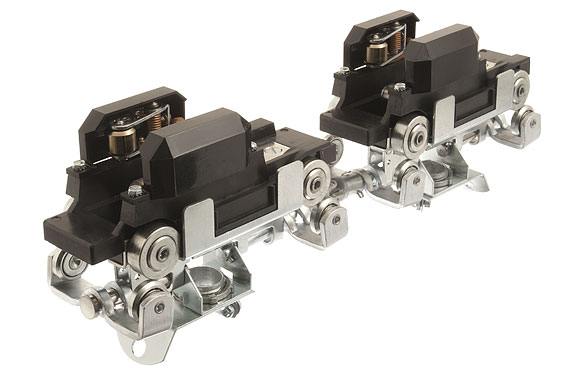
Trolleys — available in several types to meet a wide range of requirements including fusible and non-fusible types, with and without receptacles — internally track supported to provide current takeoff wherever desired.
Track sections can be supplied to form runs of any required length or contour. Hence it is “tailored-to-fit” the electric power requirements of industry, whether for modernizing an existing plant or for installation in a plant under construction.
Feedrail® “100” operates with equal safety of any required level from ceiling to floor. While the majority of installations are overhead, numerous low-level installations have been made, including some along the base of production lines. All installations have proven entirely satisfactory in operation.
Designed primarily for indoor service in essentially dry locations.
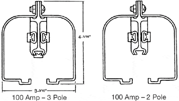
Design & Construction 2 & 3 Pole Systems
Busway and Crane & Hoist Electrification System For Movable Trolley Service
 Current Carrying Capacity
 Current Carrying Capacity
Track rating 100 Amperes (continuous); 150 Amperes (intermittent) Trolleys rated 20, 30, 40, 60 and 100 Amperes (continuous).
Voltage
600 Volts A.C. — 250 Volts D.C.
Track Supports
Malleable iron clevis type for tie rod. Fits all track accessories.
 Track
Track
 Track
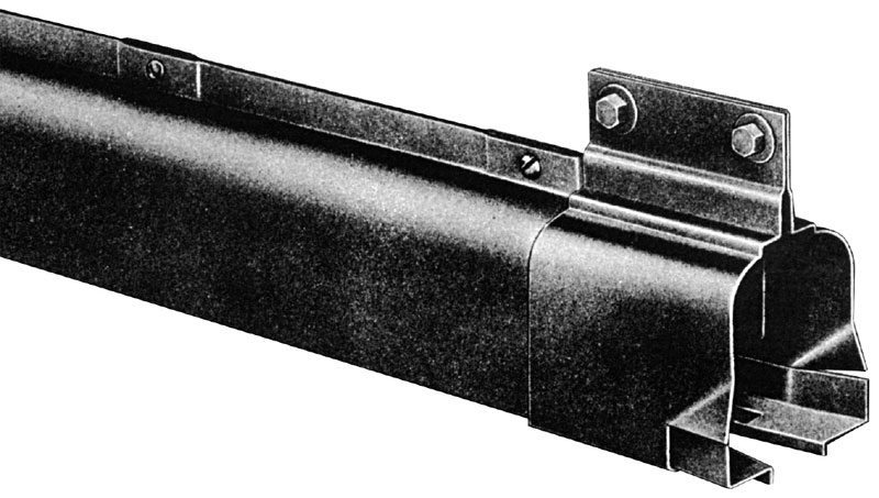
TrackTrack sections consist of a 13-gauge zinc-coated steel housing and the enclosed current carrying bus bars and insulators, all factory assembled in convenient lengths ready for easy, fool-proof installation on the job. The lower horizontal portions of the housing serve as smooth, rigid runways for the trolleys.
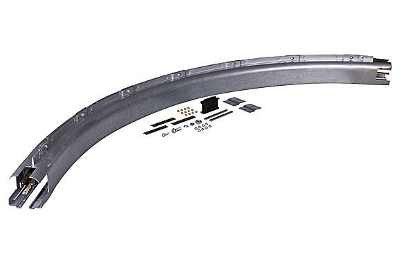
“100” Track sections are available in various types — Plain, Door, Sectionalizing, Transfer, Curved and Expansion Track Sections.
Bus bars are of hard drawn copper. They are amply proportioned to carry the specified current of 100 amperes per pole continuously, 150 amperes per pole intermittently, without overheating. Insulators are made of a high insulating and arc-resistant material. They are held in place on 9” centers by the casing.
Trolleys
Feedrail® trolleys are designed to provide stable clean power; arcing and hot spots are essentially eliminated. Stable clean power is required for trouble free operation of today’s computer controlled equipment and machinery.
Trolleys are available in fusible and non-fusible types.
Basically, all Feedrail® “100” trolleys have a chassis-insulator-contact assembly. The chassis is heavy gauge steel. The trolley wheels and guide wheels are of the ball bearing type. A substantially proportioned insulator block combines the best insulating properties with high arc-resistance.
The trolleys for the “100” track system are furnished with various types of contacts. Bronze ROLLER contacts rated 20 Amperes, Copper Graphite BRUSH contacts rated 30 Amperes and Silver Tungsten Brush contacts rated 30 and 100 Amperes.
All Feedrail® trolleys have a polarizing tab on the chassis, which, operating in conjunction with a stop within the door track, permits insertion of the trolley one way only, thereby maintaining the trolley polarity as first wired. Provision for equipment grounding is included on all trolleys.
Feedrail® “100” system Roller Contact Trolleys generally are for intermittent movement applications where speeds do not exceed 200 feet per minute. Feedrail® “100” system Brush Contact Trolleys are for more frequent moving application such as on cranes and monorails where speeds do not exceed 350 feet per minute. Where continuous movement is required at these speeds, or where low voltage (under 50 volts) or low current (under 1 Amp.) is required, consult technical service group for recommendations. Weights in excess of 40 pounds per trolley are not recommended.
Cranes and Hoists
|
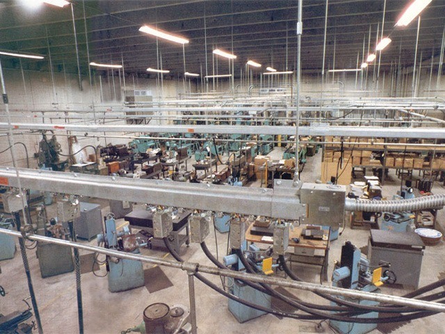
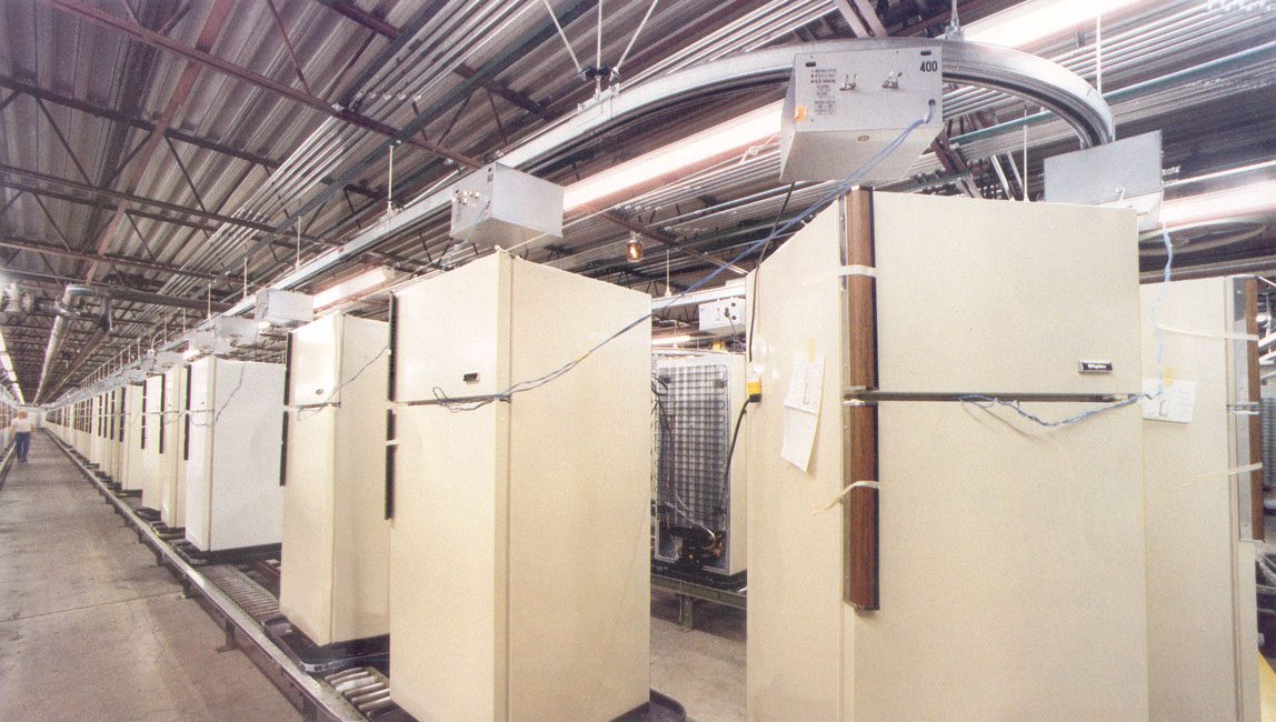
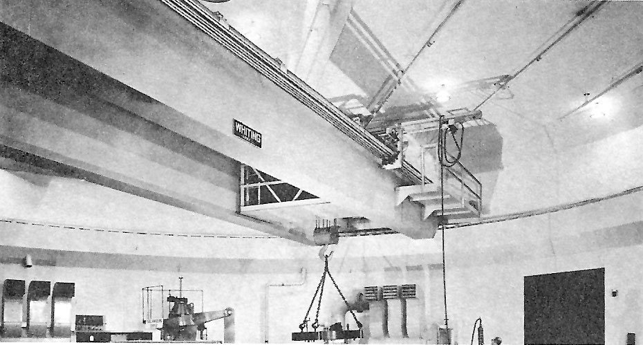
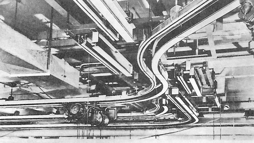
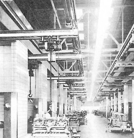
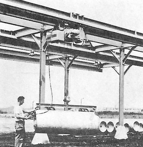
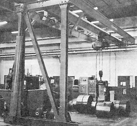
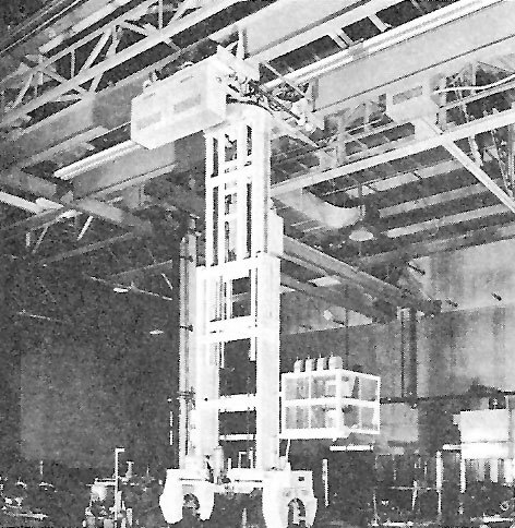
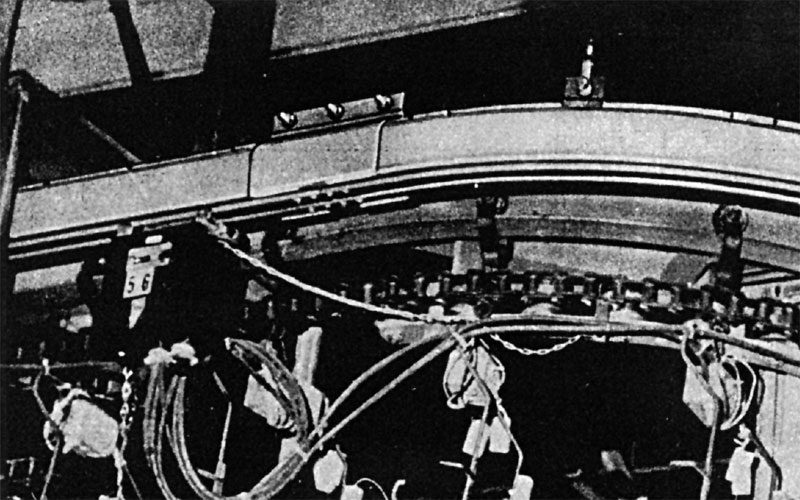
Because it eliminates the dangers and susceptibility to damage inherent in open wiring, and lowers maintenance costs, Feedrail® “100” is widely used for powering electric cranes and hoists. As these photos show it is readily adaptable to all kinds of installations, including those with curves, switches and transfers. |
|
|
|
|
|
|
|
|
|
|
Installing “100” Track
 Feedrail® “100” track, trolleys and accessories are designed for ready installation without field alteration. Any qualified electrician can do the job. No special tools are required.
Installation should begin at a transfer or switch point or at an expansion track section if these are included in a track run. Otherwise, start at the feed box (center feed or end feed) and proceed away from that point.
The following four steps should be performed in the order given:
- Install hanger rods or other supports to which Feedrail® “100” is to be attached.
- Assemble Feedrail® components. The illustrations on the following pages show the step by step procedure. In many cases the assembling of Feedrail® “100” can be facilitated by coupling two or more sections prior to rising into position.
- Attach Feedrail® to supports, making sure adjoining track sections are on the same level and in correct alignment before the track connecting bars and bus bars are secured.
- Connect electrical supply cables to terminals of feed box.
NOTE: Where Feedrail® equipment has been ordered to the job site in advance of actual installation, the equipment should be carefully stored indoors in a clean, dry area.
Feedrail® “100” is designed primarily for indoor service in essentially dry locations.
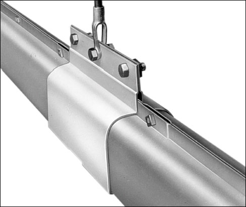
Installing Transfer Track
 Transfer Track sections are similar to Plain Track sections except that one or both ends are flared and have a tapered insulator serving as a guide for entrance of the trolleys.
On installations having transfer points, (turntables, slide or tongue switches, hangar door tail-gates, etc.) the Transfer Track sections should be installed first so that proper gaps can be set. These gaps between Transfer Track sections should not exceed ¼ inch.
(Transfer Track sections for use on turntables and slide switches, are not stock items but are manufactured specifically to conform to given dimensions.)
Where motor propelled hoists are used on runs which include transfer points, it is necessary to use two electrically interconnected trolleys. The two trolleys must be spaced sufficiently so that current is maintained to one trolley while the other crosses the transfer point. Duplex Transfer Type Trolleys have been designed particularly for this application.
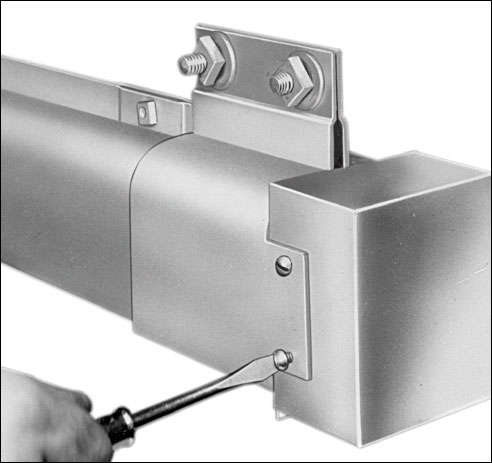
Transfer Track sections at transfer points must be aligned accurately, both horizontally and vertically. They must be supported at the transfer ends by an FR-124 Transfer Point Hanger Set. (Hook bottoms of Transfer Point Hanger Set into slots in the under edges of the track housing. Bring the plates together and fasten to support with bolts as shown).
In every case the mounting of Transfer Track sections should be designed to insure a rigid installation. They should be sway braced to maintain alignment.
Sections are installed and coupled to adjoining track sections as shown in Joining Sections With Coupling Plate Set FR-102.
Building Expansion Track
At least one Expansion Track section should be installed in each 400 ft. of track run to compensate for the cumulative differences in expansion and contraction between the steel casings and copper bus bars. Additional Expansion Track sections may be required if the installation is subjected to a wide range of temperature changes.
Expansion Track sections must be used wherever an installation is made across a building or structural expansion joint.
The standard 10' Expansion Track section is designed to provide 2” of expansion and 2” of contraction above and below the normal 10' length, at 75°F. At the time of installation, the length of the Expansion Track section must be set in accordance with the table below.
When used at points other than a building or structural expansion joint to compensate for unequal expansion or contraction between the steel track housing and copper bus bars, support the Expansion Track section by the coupling plates at each end and by the center support plates from suitable support brackets.
When used across a building expansion joint, center the Expansion Track section across the building expansion joint and support at each end from coupling plates and from the center support plates. Center support must be on the same side of the building expansion joint as the side of the expansion section stenciled “STATIONARY.”
Length Settings for Standard 10' Expansion Track |
|||
|
Installation Temperature |
Distance in Feet * |
||
|
100 |
200 |
400 |
|
|
100°F |
9'11-3/16” |
9'11-5/8” |
9'11-¼” |
|
75°F |
10' |
10' |
10' |
|
50°F |
10'3/16” |
10'3/8” |
10'¾” |
|
25°F |
10'3/8” |
10'¾” |
10'1-½” |
|
* Distance Represents: |
|||
“100” Expansion Track Design Data, Usage and Settings
Coefficients of thermal expansion (K) (Inches per foot per degree F) |
||
|
Steel |
Copper |
Difference |
|
.0000768 |
.0001116 |
.0000348 |
To determine expansion (or contraction) of system casing (steel) or bus bars (copper):
Expansion = K x ΔT x L
K= Constant (from table above)
L= Length (in feet)
ΔT= Temperature change (°F)
A) A straight run of “100” track has sufficient freedom of movement between copper bus bars and steel casing to accommodate an expansion or contraction of 3/8 inch of the copper bus over and above that of the steel casing. Where a Feedrail® installation will be subjected to a high or low temperature, such that the expansion or contraction of the copper bus bars (from nominal 75 °F) will exceed the steel track casing expansion or contraction by 3/8 inch, an expansion section must be used.
Example: In a 250 foot run of “100” Feedrail® track which will be subjected to a low temperature of 15 °F, the difference in contraction between the copper bus bars and the steel track casing due to the 60 °F. temperature drop from a nominal 75 °F. will be
.0000348×250 ft. x 60 °F. temp
Difference = .522 inches
Since this is in excess of the maximum of 3/8 inch (.375”) permitted, an expansion section must be used in the run.
B) It is recommended that at least one expansion track section be installed in each 400 ft. of track run, even if only minor temperature fluctuations are expected in the area in which the Feedrail® is installed.
C) Expansion track sections must be used wherever an installation is made across a building expansion joint to prevent the building movement from causing undue stresses on the Feedrail® system.
D) The “100” Expansion joint is normally made to a nominal length of 10'-0'' and is designed to operate within the limits of 9'-10'' to 10'-2'' length of the steel casing. In addition to the above movement permitted by the steel casing, the copper bus bars are permitted 50% additional movement with respect to the casing so that the normal difference in expansion or contraction between the casing and bus bars can be accommodated be the expansion joint.
E) The air temperature at the time of the actual installing of a Feedrail® system will influence the setting of a Feedrail® expansion track section. They should be set in accordance with the table in the Building Expansion Track section directly above this section.
Elevated Temperature Use Of FR-100 System
Below is a data sheet giving the U/L approved temperature usage of Feedrail® 100 systems and the temperature restrictions based on the properties of the materials used in construction of the equipment.
The U/L approval does not apply to use in ambients over 40°C (104°F.)
ELEVATED TEMPERATURE USE- RESTRICTIONS
Feedrail® FR-100 TRACK SYSTEM
RATED AMP CONTINUOUS- 150 AMP. INTERMITTANT
Feedrail® “100” is listed for its continuous ampacity rating by the Underwriters' Laboratories based on a maximum temperature rise of the bus bars of 54°F (30°C) above 104°F (40°C) ambient temperature. In order that its maximum life under continuous operating conditions might be realized, operation at elevated ambients require operation at lower ampacity as follows:
|
AMBIENT TEMPERATURE |
INTERMITTANT RATING |
AMPACITY CONTINUOUS |
% OF CONTINIOUS RATING |
|
104°F (40°C) |
150 Amps. |
100 Amps. |
100% |
|
122°F (50°C) |
127 Amps. |
85 Amps. |
85% |
|
140°F (60°C) |
87 Amps. |
58 Amps. |
58% |
|
154°F (68°C) |
37 Amps. |
25 Amps. |
25% |
In the event that the Feedrail® “100” equipment is subject to higher ambient temperature, the following information as to its operating life is offered as a guide:
A) “Rated life” based on insulation life vs. temperature is considered in excess of 100,000 hours (11.4 years) of service at rated Ampacity. (Not applicable to wearing parts such as trolley wheels and contacts).
B) Increasing the system temperature, either by increasing the ambient or the heating effect of the current through the bus bars, will shorten the life of the system by the following estimated amount:
|
SYSTEM TEMPERATURE |
LIFE EXPECTANCY % OF NORMAL |
|
176°F (80°C) |
50% |
|
194°F (90°C) |
25% |
|
212°F (100°C) |
12% |
The “100” system should not be operated so as to have any part reach 250°F (121°C). Consult factory for other conditions.
C) Factors which often accompany increased ambients (fumes, corrosion, etc.) contribute to the reduction of the service life of the equipment, often to a greater extent than temperature increases
D) Trolleys used in ambients over 104°F (40°C) should have “sealed” wheels and brush contacts, and use wire suitable for the maximum temperature expected.
* Intermittent Duty Cycle Rating based on one minute “ON”, one minute “OFF”.
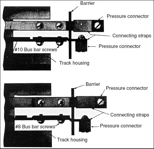
Coupling Sections With Center Feed Box FR-103
|
|
|
|
|
|
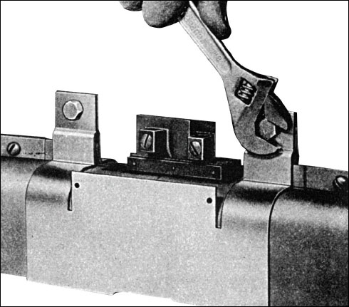
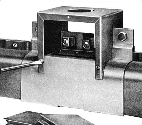
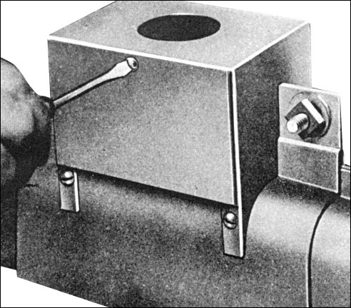
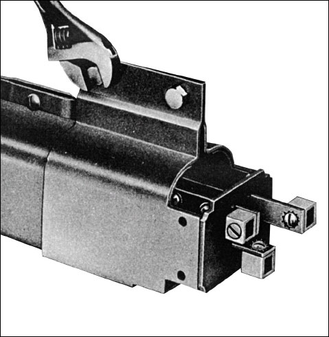
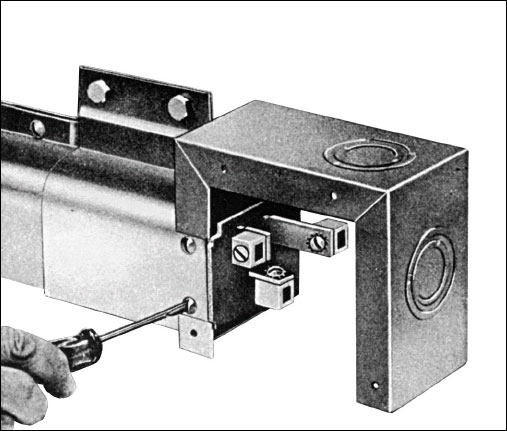
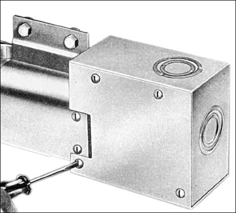
Mounting End Feed Box FR-109
|
|
|
|
|
|
Mounting Dead End Cap FR-107
|
|
|
Installing Sectionalizing Track
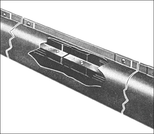 Sectionalizing Track sections are used to electrically isolate parts of a track run while permitting movement of the trolleys through that portion of the track.
All Sectionalizing Track sections are coupled in the same manner as Plain Track, shown in Joining Sections With Coupling Plate Set FR-102.
NOTE: The standard sections described have internal insulators of a size which do not prevent the interrupting of the current to the trolley. The current is not only maintained through the trolley but the circuits on both sides are electrically tied together through the trolley contacts as the trolley passes the sectionalizing insulator.
Other special sectionalizing track sections which are used in particular applications do break the current to the trolley. In these cases, two electrically connected trolleys must be used. They must be spaced sufficiently apart so that the contacts of one will be on the bus bars while the contacts of the other are passing the insulator. Unless connected in this manner, power will not be maintained to the trolley contacts as they cross the insulators and arcing at the trolley contacts will occur. Sectionalizing track sections must not be used as a circuit interrupting device.
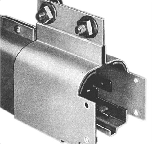
Joining Sections With Coupling Plate Set FR-102
|
|
|
|
|
|
Joining Curved Track Sections
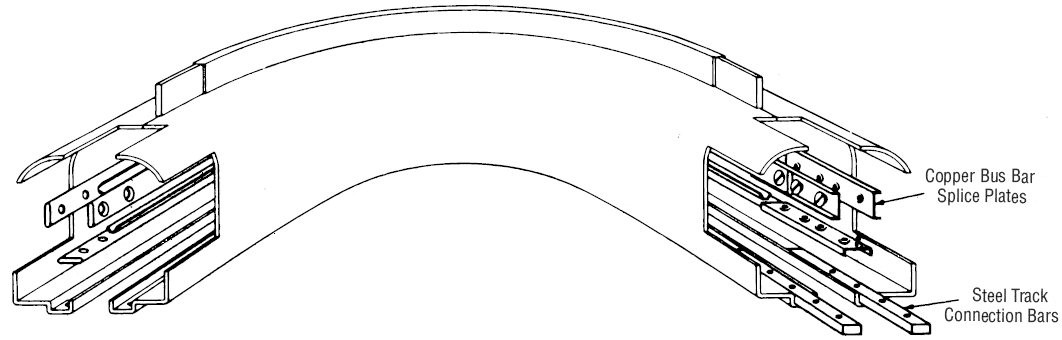
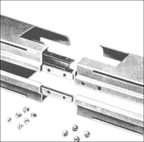
For proper assembly of the curved track, the copper bus bar splice plates and steel track connection bars are required on either the right hand or left hand end of the curved track section.
Curved track sections are furnished with separate copper bus bar splice plates and steel track connection bars. They are supplied in a bag strapped to the track section. The above illustration shows them assembled to the right hand end of the curved track section.
Before putting the copper bus bar splice plates on to the curved track section, place the loose insulator (which comes in a cloth bag fastened to the curved track section) between the curved track end and the first insulator. (See illustration above).
The below illustrations show to which end the copper bus bar splice plates and steel track connection bars must be assembled.
If the straight track to be joined to the curved track has this type of end.
The copper bus bar splice plates and steel track connection bars must be attached to the curved track to form this type of end.
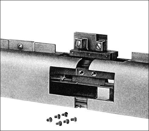
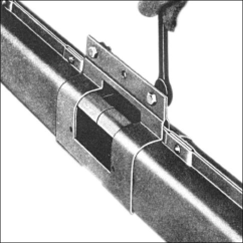
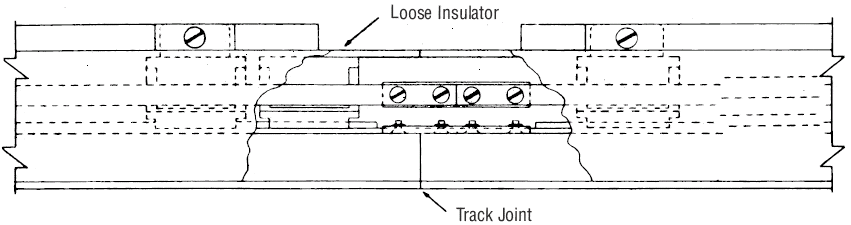
After copper bus bars and steel track casings have been connected, assemble coupling plate set to track by hooking bottoms of coupling plates into slots under edges of track casings, bring plates together, insert and tighten bolts. When complete the joint will look like the above.
If the straight track to be joined to the curved track has the above type of end, the curved track must have this type of end shown below.
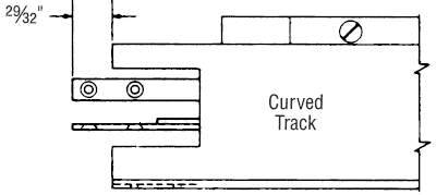
The connection of the straight track to the curved track, as shown above, is made without the use of the copper bus bar splice plates or the steel track connection bars. (These are used at the other end of the curved track section.)
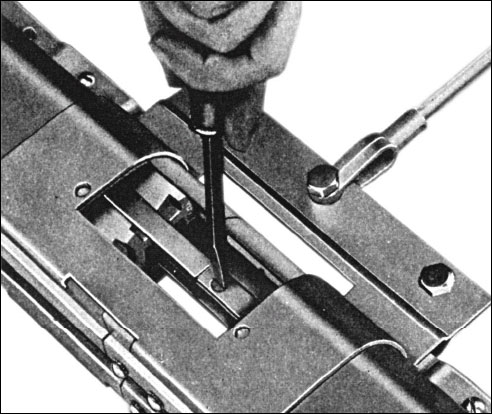
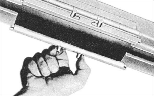
Inserting Trolleys
|
|
|
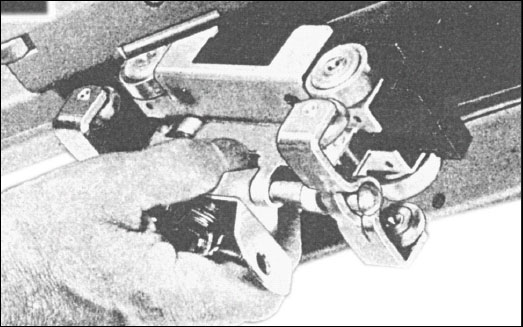
Mounting of Crane and Hoist Type Trolleys
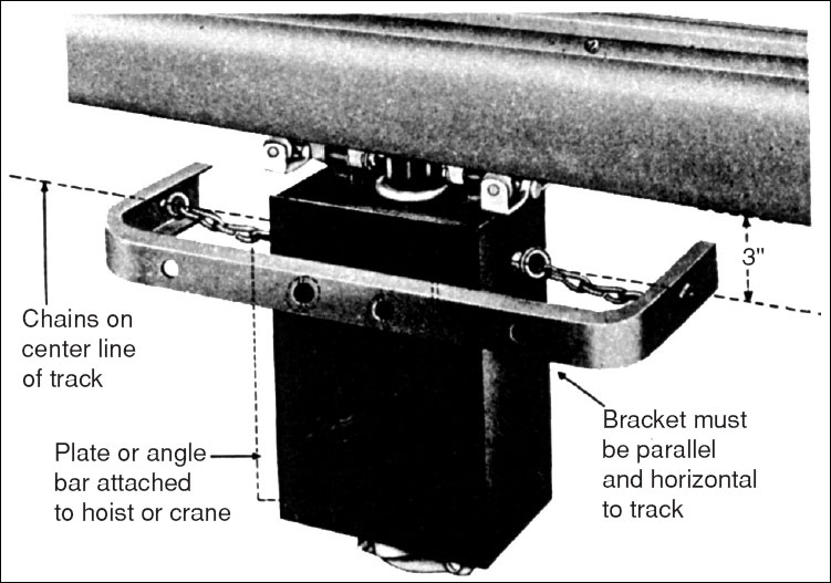
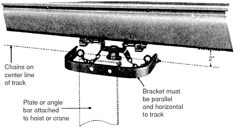 Trolleys for use on Cranes and Hoists (Crane and Hoist Trolleys) are equipped with a pulling bracket with chain linkage. Brackets must be attached to the hoist or crane bridge in such a manner that the chains are on the center line of the track and the bracket is parallel to the track and 2” below the track. Flexible rubber covered cables must be used for electrical connection to each trolley.
Mounting of Special Service Trolleys
 Special Service Trolleys for use on straight track runs are equipped with a pulling bracket with chain linkage. Brackets must be attached to the hoist or crane bridge in such a manner that the chains are on the center line of the track and the bracket is parallel to the track and 3” below the track. Flexible rubber covered cables must be used for electrical connection to each trolley.
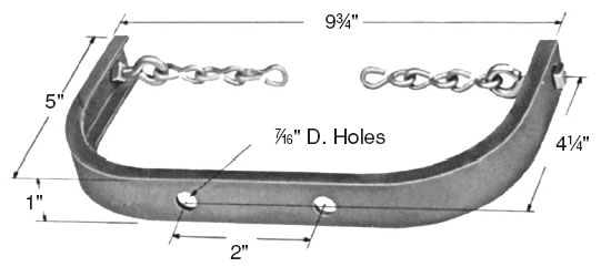
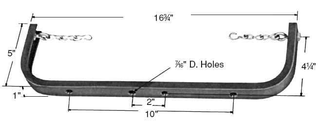
Mounting Dimensions of Trolley Pulling Rackets
|
For use on Standard and Short Radius Crane and Hoist Type Trolleys without Receptacles and on Plain Transfer Type Trolleys without Receptacles. |
For use on Special Service Trolleys, on Standard and Short Radius Crane and Hoist Type Trolleys with Receptacles, on Duplex Crane and Hoist Type Trolleys, on Plain Transfer Type Trolleys with Receptacles and on Duplex Transfer Type Trolleys. |
Installation Planning
Before a Feedrail® system can be planned or an estimate of the cost prepared, the electrical and mechanical requirements that the system must meet should be known. The following outlines list the basic data needed for all applications and the additional data required for various specific applications.
Basic For All
- Describe in detail the purpose of the Feedrail® “100” system. Will it be used with existing equipment?
- What is the voltage of the available power source and type of current (A.C. or D.C.)? If A.C., is it single or three phase?
- Details about any special requirements or conditions which the installation must meet such as moisture, corrosive fumes, high or low temperatures, etc.
For Electric Cranes
- Sketch giving number, location, length of crane runways and length of bridge. Show location of building expansion joints, if any.
- How many conductors will be required on each bridge run? — How many for power? — for control? Ho w much current must each conductor carry?
- What is the maximum travel speed of the bridge? — of the hoist?
- List of the crane’s motors — main hoist, auxiliary hoist, bridge travel, trolley travel — giving the type (D.C., wound rotor, squirrel cage, etc.) of each motor and its horsepower and full-load ampere rating.
For Moving Test Lines
- Plan view sketch with dimensions showing the length of straight sections and radii of any curves. Indicate the number of outlets required. If there are any sections along the run where test current will not be required, indicate their location and extent.
- What type of equipment will be tested?
- Give weight of units to be supported by the system.
- What amperage range and what fusing arrangements will be required?
For Hanger Doors
- Sketch with dimensions to show the location and space available for the Feedrail® system. Indicate range of roof deflection due to snow loads, temperature changes, etc.
- Plan view showing exact sizes and locations of tailgates. Give location of expansion joints, if any, in the upper door guides and in the hangar roof structure. Indicate size and number of doors and pattern of door movements.
- List the number of conductors required and give voltage and amperage requirement of each. Give horsepower and full load current rating of the motors.
For Electric Hoists
- Plan view sketch of the rail system on which the hoists will travel, giving length of run and dimensions of any switches. What is the minimum distance from Feedrail® to monorail in order to clear hoist? Show location of building expansion joints.
- How many hoists will be used and what is the horsepower and full load current rating of each? Include horsepower and full load current rating of travel motors of any of the hoists that are motor propelled. What are the maximum travel speeds?
For Portable Tool and Conveyor Assembly Lines
- Sketch with dimensions showing the location and space available for the system. Show location of building expansion joint, if any.
- What type of portable tools will be used, how many, and what is the horsepower and full-load current rating of each?
- Is each tool to be fused individually? Give weight of any tools to be supported by the system.
- List any other equipment that will be operated from the Feedrail® system with the horsepower and full-load current rating of each unit.
- If power for driving any conveyors is also to be taken from the Feedrail® system, what is the horsepower and full-load current rating of each motor?
For Special Requirements
- Plan view sketch with all dimensions which are necessary to make clear the location and extent of the Feedrail® “100” system and the radii of any curves it may contain. Show the location of the power source.
- Full details about equipment which will be operated from the system, including:
- Horsepower and full-load current rating of any electrical motors.
- Weight of any equipment to be supported by the system.
- Fusing arrangements required.
- Number of outlets needed.
Preventive Maintenance
At all times Feedrail® equipment should be so protected and maintained as to be kept clean and dry.
Before the Feedrail® system is placed in operation, it should be thoroughly checked for horizontal and vertical alignment, adequate track support, and free movement of trolley travel throughout the entire track run. All track, bus bar and feed connections should be mechanically tight. The system should be checked for possible grounds or short circuits. Any paint, grease, or other foreign matter accumulated during construction should be removed from the bus bars, insulation and track interior. Blow out all dust and other loose particles from inside the track.
Expansion sections, when used, must be properly adjusted, located and supported in accordance with installation instructions. Check bus bars and casing for accurate alignment.
Feedrail® is both an electrical and a moving mechanical system and therefore should be included as a part of your Preventive Maintenance Program.
Electrical maintenance requires:
- Keeping the System dry and clean to prevent electrical leakage or “shorts” across the insulation.
- Maintaining electrical continuity by keeping bus bar contact surfaces clean and joints tight.
Mechanical maintenance requires:
- Preventing excessive wear
- Replacing parts showing excessive wear.
The following Preventive Maintenance procedure, periodically performed, is recommended:
- Remove, thoroughly clean all trolleys and lubricate the wheels. Feedrail® recommends Grade #1 Bearing Grease. This is softer grease than #2 and allows the grease to penetrate the bearings easier. Inspect contacts for excessive wear. Replace worn wheels and contacts.
- Clean bus bars with Feedrail® Bus Bar Cleaner.
- Blow out all foreign particles which have accumulated inside the track.
- Check trolleys for free movement within the track.
- Check all track supports, track joints, bus bar and feed connections for tightness.
This procedure should be repeated at regular intervals, consistent with the severity of the operations and usage of the system. Plants operating two or three shifts will require more frequent inspection of the Feedrail® equipment.
Feedrail® is not normally recommended for installations subject to vibration, frequent electrical overload, corrosive fumes and other abnormal conditions. However, should such conditions exist, more frequent inspection and main– tenance will be required.
Before additional electrical loads are added to the system it should be determined that sufficient capacity is available.
Basic Dimensions/Mounting Methods of Feedrail® ‘100’ Assembly
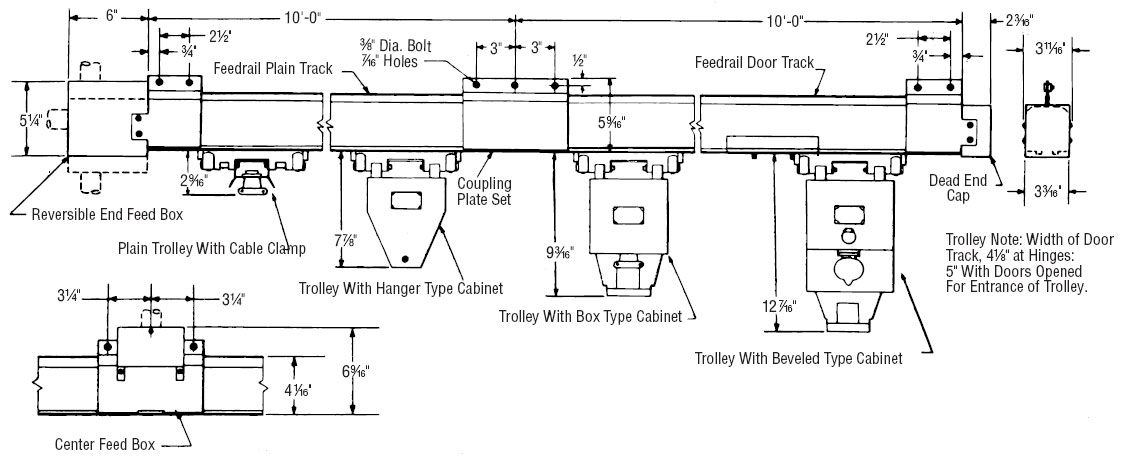
Examples of the methods commonly used for mounting Feedrail® “100” systems track runs are shown. These methods can be used in existing plants as well as in new buildings. Engineers and contractors will readily be able to devise other methods to suit special installations. In every case the mounting should be designed to insure a rigid installation in both horizontal and vertical alignment.
As an aid in planning mountings, the basic dimensions of the “100” systems are shown. These are offered as a guide only.
Typical Specification
The Trolley Busway System (Crane and Hoist Electrification System) shall be of metal enclosed type with internally track supported trolleys as manufactured by:
Genuine Feedrail®
Industrial Products
The System shall have a voltage rating of 600 Volts A.C. or 250 Volts D.C. (2 pole) (3 pole) and a continuous current carrying capacity of 100 Amperes per Pole: (When used as a Crane and Hoist Electrification System, the System shall be rated at 100 Amperes continuous service and 150 Amperes intermittent service). The full current carrying capacity of the system shall be maintained throughout.
The System shall permit longitudinal movement of the housing and bus bars, independent of each other, in order to allow for unequal expansion and contraction as a result of temperature changes.
The System shall consist of standardized, interchangeable, Feedrail® units — track sections, coupling sets, dead end caps, track hangers and power takeoff trolleys, as called for on the plans.
Track sections shall be pressed 13 gauge zinc-coated sheet steel enclosures having a continuous slot in the bottom. Rolled or drawn copper bus bars, capable of carrying 100 Amperes per pole continuously without overheating, shall be mounted within the steel enclosure on arc-resistant insulators.
Door track sections shall include two hinged doors in the bottom for insertion and removal of trolleys. Door openings shall have a mechanical polarization to insure proper polarity of the trolleys.
Track supported trolleys shall be Cat. No.__________________________ as listed in the Feedrail® Catalog. They shall have a zinc-plated sheet steel chassis with metal wheels for support. Horizontal guide wheels shall run in the slot of the Feedrail® track to prevent slewing and maintain alignment. Spring-loaded roller, (or brush) contacts shall be mounted on arc-resistant insulation. When inserted in Feedrail® track, the contacts shall align with the bus bars at all times.
Trolleys shall be mechanically polarized with respect to door track sections.
Build Your Feedrail FR100 Series Trolley Service System
All of the components you’ll need to build a brand new Feedrail FR100 Series system have been organized below by category. It is recommended that you start with Track Sections and work your way through each category in the order they’re presented. If you have any questions, please contact us and one of our highly trained Feedrail specialists will respond shortly.
 Track Sections |
 Track Accessories & Hangers |
 Trolleys |
 Track & Busway Cleaning Tools |
 Ever-Lok Wiring Devices |
 Replacement Parts |
Shop for Feedrail FR100 Series Trolley Service System Components, Parts & Accessories
All components, parts and accessories for the Feedrail FR100 Series Trolley Service System can be found below. Use the product filter menu to narrow your search.
Track Sections
FR100 Track
 Continuous Rating:
100 Amperes — 600 Volts A.C. — 250 Volts D.C.
Intermittent Rating:
150 Amperes — 600 Volts A.C. — 250 Volts D.C. (1 minute off, 1 minute on)
Note: 10 feet is standard length. Shorter lengths furnished on special order; minimum length 20 inches.
Track Sections, Door Track
Door track sections are identical to plain track sections except with the addition of two hinged doors in the bottom for the insertion and removal of trolleys. When closed, the doors are securely locked and accurately aligned with the rest of the track to form an uninterrupted runway for the trolleys. Hinged doors are easy to open or close. No tools are required. Pressing pins together against spring pressure disengages locking bolts. Door openings are polarized so trolleys can be inserted only one way.
Track Sections, Curved Track
Curved sections are of the same general specifications as plain track. All standard curved track sections are full 90° curves and have an additional 4” of straight track on each end for coupling. Special sections with different degrees of arc and radius from those listed below can be furnished to order. Minimum radius, 2'6”. Maximum length per single curved section is 12'6”. 90° curves. Sections complete with Bus Bars
Track Sections, Sectionalizing Track
Sectionalizing Track sections isolate portions of a track run. They are the same as Plain Track sections except at the center of the track each bus bar is interrupted by an air gap. The bus bars are so formed and positioned by a special insulator that all trolleys smoothly cross the air gap while maintaining electrical continuity. The circuits on both sides of the gap are momentarily tied together through the trolley contacts as the trolley passses the air gap. Special sectionalizing Track sections are made that do interrupt the current to the trolley. When used, there require two electrically connected trolleys to maintain current through the trolley at all times. They must not be used as a circuit interrupting device. Sections complete with Bus Bars.
Track Sections, Expansion Track
Continuous Rating:
100 Amperes — 600 Volts A.C. — 250 Volts D.C.
Intermittent Rating:
150 Amperes — 600 Volts A.C. — 250 Volts D.C. (1 minute off, 1 minute on)
Transfer Sections
Transfer sections are similar to plain track sections, except have one or two ends flared for use at points of transfer on slide switches, turn-tables, etc. (transfer track sections for use on turn-tables, or slide switches ar enot stock items but are manufactured specifically to meet given dimensions). A nose insulator at the transfer point serves as a guide for the proper entrance of the trolley. Curved transfer sections with one or both ends flared, with or without doors, and with feed-in boxes installed can be furnished on special order.
Track Accessories
Trolleys
Feedrail® trolleys are designed to provide stable clean power; arcing and hot spots are essentially eliminated. Stable clean power is required for trouble free operation of today’s computer controlled equipment and machinery. To learn more about FM & FX Multi-Conductor Series trolleys, click here.
FR100 Series (Feedrail® '100') — Trolley Design and Construction
The same efficient engineering and clean-cut construction, that is a hallmark of the entire Feedrail system, is evident in the internally track supported “100” trolleys. They are available either non-fusible or fusible, with or without recepticles, fully assembled ready for insertin in the track. Fusible trolleys and trolleys with recepticles are factory wired. Other trolleys are furnished with crimp-style lugs.
Basically, all Feedrail “100” trolleys have the chassis-insulator-contact assembly listed below. The chassis is of one-piece heavy gauge steel. It is equipped with ball-bearing wheels for supports; horizontally mounted ball-bearing guide wheels running in the slot of the track to prevent slewing, and ball-bearing wheels on pivoted arms of the undercarriage to control upthrust. This wheel combination assures smooth easy running trolleys.
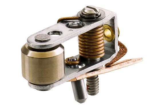
The insulator contact assembly consists of a substancially proportioned hot-molded, non-tracking, arc quenching insulator block on which arms with contact brushes (or rollers) are mounted and held in true alignment with the track bus bars. Torsion springs, one on each arm, keep the brush (or roller) in contact with the bus bar. The body is entirely closed between the contact sida and the chassis to prevent any foreign material entering between the wiring terminals and chassis. The contacts are easily replaceable from the top without requiring the removal of the body from the chassis or disturbing the existing wiring of the trolley.
Feedrail “100” trolleys are furnished with two types of contacts: Copper Graphite BRUSH contacts rated 30 Amperes, and Bronze ROLLER contacts rated 20 Amperes.
The special service trolleys have silver-tungsten contacts. Other trolleys can be furnished with silver-tungsten contacts on request.
All Feedrail “1--” trolleys have a polarizing tab on the chasis which, operating in conjunctin with a stop within a door track, permits insertion of the trolley one way only, thereby maintaining the trolley polarity as first wired. Provision for equipment grounding is included on all trolleys.
The standard Feedrail “100” non-cabinet trolleys are equipped with trolley brackets to facilitate pulling by means of tow chains. Crane and Hoist and Transfer trolleys have an additional pulling bracket and chain linkage for attachment tot he hoist or to the crane bridge. Standard Feedrail cabinets of various types are available for suspension fromt he trolley chasis. A simple suspension design makes it possible to remove and mount cabinets in a matter of minutes should a change to another type become desirable. Weights in excess of 40 pounds per trolley are not recommended.
Feedrail “100” Roller Contact trolleys generally are for intermittent movement applications where speeds do not exceed 200 feet per minute. Feedrail “100” Brush contact trolleys are for more frequent moving applications such as on cranes and monorails where speeds do not exceed 350 feet per minute.
These trolleys are not for use on transfer track. Fusible trolleys take National Electric Code Standard Cartidge fuse of the same voltage rating of the trolley (Fuses not included).
Crane and Hoist Trolleys
HORSEPOWER RATINGS are for induction type and squirrel cage motors with usual speeds and normal torque characteristics. HORSEPOWER RATINGS do not apply for Wound Rotor Motors with secondary speed control no for Motors with especially low speeds or high torque characteristics. Consult technical service group for recommendations.
TROLLEYS and RECEPTACLES are not intended for opening and closing circuits under load.
Transfer Type Trolleys
Transfer type tolleys are especially designed to facilitate crossing of gaps between crane bridges and spur runs or between slide switch sections and the main run. Where motor propelled hoists are used on runs which include transfer points, duplex type transfer trolleys must be used to insure continuous current while crossing the transfer points.
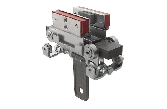
100 Ampere Special Service Trolleys
For use on straight track only without transfer gaps.
Typical of Feedrail’s advanced engineering design, this single unit trolley combines all the essential features of the standard trolley series with the special requirements of high power full rated take-off. It is ideal for heavy tonnage travelling cranes, hoists and similar equipment.
These trolleys differ in construction details from the general trolley description in that the contact assembly consists of three substantially proportioned mechanically strong arc-resisting blocks on which silver tungsten brush contacts, one per pole, are mounted and kept in continuous contact with the bus bars by individual compression springs. Solderless type pressure connectors are within a heavy gauge sheet steel terminal box. A cable clamp is provided as a pulling bracket with chain linkage to make the positive attachment to the equipment being powered.
Cleaning Tools
With these trolley mounted tools, bus bars can be quickly cleaned. They are inserted in the door track openings and pushed back and forth. All bus bars are cleaned at the same time. For use on all track sections.
CAUTION! POWER TO BUSWAY MUST BE TURNED OFF WHILE USING CLEANING TOOLS.
Ever-Lok Wiring Devices
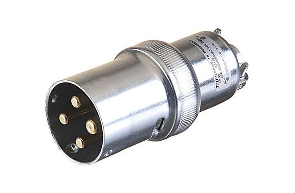
Used for connecting tools and other equipment to Feedrail® trolleys. These units are available in various styles — fused and non-fused self-locking plugs, receptacles and connectors — to meet the varied demands of industry. Illustrated here are those most frequelntly used with Feedrail® equipment. All units are ploarized to prevent improper connection.
Replacement Parts
-

-

-

-

-

-


Feedrail 10’ Straight Track – 3 Pole, 100 Amp
Item Number: FR100
10 foot straight track section. 3 pole, 100 amp, 600 volt AC / 250 volt DC. Fits Feedrail FR100.

Feedrail 5’ Straight Track – 3 Pole, 100 Amp
Item Number: FR1005
5 foot straight track section. 3 pole, 100 amp, 600 volt AC / 250 volt DC. Fits Feedrail FR100.

Feedrail 10’ Straight Track with Door – 3 Pole, 100 Amp
Item Number: FR101
10 foot straight track section with trolley door. 3 pole, 100 amp, 600 volt AC / 250 volt DC. Fits Feedrail FR100.

Feedrail Curved Track - 2' 6" Radius, 3 Pole, 100 Amp
Item Number: FR115
Curved track, 2' 6" radius (to center line). 3 pole, 100 amp, 600 volt AC / 250 volt DC. Fits Feedrail FR100.

Feedrail Curved Track - 3' Radius, 3 Pole, 100 Amp
Item Number: FR113
Curved track, 3' radius (to center line). 3 pole, 100 amp, 600 volt AC / 250 volt DC. Fits Feedrail FR100.
Feedrail Curved Track - 3' 6" Radius, 3 Pole, 100 Amp
Item Number: FR116
Curved track, 3' 6" radius (to center line). 3 pole, 100 amp, 600 volt AC / 250 volt DC. Fits Feedrail FR100.
Feedrail Curved Track - 4' Radius, 3 Pole, 100 Amp
Item Number: FR117
Curved track, 4' radius (to center line). 3 pole, 100 amp, 600 volt AC / 250 volt DC. Fits Feedrail FR100.
Feedrail Curved Track - 4' 6" Radius, 3 Pole, 100 Amp
Item Number: FR114
Curved track, 4' 6" radius (to center line). 3 pole, 100 amp, 600 volt AC / 250 volt DC. Fits Feedrail FR100.
Feedrail Curved Track - 5' Radius, 3 Pole, 100 Amp
Item Number: FR118
Curved track, 5' radius (to center line). 3 pole, 100 amp, 600 volt AC / 250 volt DC. Fits Feedrail FR100.
Feedrail Curved Track - 5' 6" Radius, 3 Pole, 100 Amp
Item Number: FR111
Curved track, 5' 6" radius (to center line). 3 pole, 100 amp, 600 volt AC / 250 volt DC. Fits Feedrail FR100.
Feedrail Curved Track - 6' Radius, 3 Pole, 100 Amp
Item Number: FR119
Curved track, 6' radius (to center line). 3 pole, 100 amp, 600 volt AC / 250 volt DC. Fits Feedrail FR100.
Feedrail Curved Track - 6' 6" Radius, 3 Pole, 100 Amp
Item Number: FR121
Curved track, 6' 6" radius (to center line). 3 pole, 100 amp, 600 volt AC / 250 volt DC. Fits Feedrail FR100.
Feedrail Curved Track - 7' Radius, 3 Pole, 100 Amp
Item Number: FR120
Curved track, 7' radius (to center line). 3 pole, 100 amp, 600 volt AC / 250 volt DC. Fits Feedrail FR100.
Feedrail Curved Track - 7' 6" Radius, 3 Pole, 100 Amp
Item Number: FR112
Curved track, 7' 6" radius (to center line). 3 pole, 100 amp, 600 volt AC / 250 volt DC. Fits Feedrail FR100.

Feedrail 10' Sectionalizing Track - 3 Pole, 100 Amp
Item Number: FR147
10 foot sectionalizing track. 3 pole, 100 amp, 600 volt AC / 250 volt DC. Fits Feedrail FR100.
Feedrail 10' Sectionalizing Track with Door - 3 Pole, 100 Amp
Item Number: FR148
10 foot sectionalizing track with trolley door. 3 pole, 100 amp, 600 volt AC / 250 volt DC. Fits Feedrail FR100.

Feedrail 10' Expansion Track - 3 Pole, 100 Amp
Item Number: FR155
10 foot expansion track. 3 pole, 100 amp, 600 volt AC / 250 volt DC. Fits Feedrail FR100.

Feedrail 10' Transfer Track Section - 3 Pole, 100 Amp
Item Number: FR195
10 foot transfer track, two ends flared. For FR100 Series (Feedrail(R) '100'). Note: Sections complete with bus bars and a center feed box FR-103. 3 pole, 100 amp, 600 volt AC / 250 volt DC.
Feedrail 10' Transfer Track Section with Door - 3 Pole, 100 Amp
Item Number: FR196
10 foot transfer track with trolley door, two ends flared. For FR100 Series (Feedrail(R) '100'). Note: Sections complete with bus bars and a center feed box FR-103. 3 pole, 100 amp, 600 volt AC / 250 volt DC.
Feedrail 10' Transfer Track without Bus Bars, One End Flared
Item Number: FR132
10' transfer track, one end flared, without bus bars. For FR100 Series (Feedrail(R) '100').
Feedrail 10' Transfer Track without Bus Bars, with Door, One End Flared
Item Number: FR133
10' transfer track, one end flared, without bus bars, with trolley door. For FR100 Series (Feedrail(R) '100').
Feedrail 10' Transfer Track without Bus Bars, Two Ends Flared
Item Number: FR142
10' transfer track, two ends flared, without bus bars, with trolley door. For FR100 Series (Feedrail(R) '100').
Feedrail 10' Transfer Track without Bus Bars, with Door, Two Ends Flared
Item Number: FR143
10' transfer track, two ends flared, without bus bars, with trolley door. For FR100 Series (Feedrail(R) '100').
Feedrail 10' Transfer Track with Offset Bus Bar Ends, One End Flared - 3 Pole, 100 Amp
Item Number: FR185
10 foot transfer track, one end flared with offset bus bar ends. For FR100 Series (Feedrail(R) '100'). Note: Sections complete with bus bars. 3 pole, 100 amp.
Feedrail 10' Transfer Track with Offset Bus Bar Ends & Door, One End Flared - 3 Pole, 100 Amp
Item Number: FR186
10 foot transfer track with trolley door, one end flared with offset bus bar ends. For FR100 Series (Feedrail(R) '100'). Note: Sections complete with bus bars. 3 pole, 100 amp.
Feedrail 10' Transfer Track, One End Flared with Plain Bus Bar Ends - 3 Pole, 100 Amp
Item Number: FR187
10 foot transfer track, one end flared with plain bus bar ends. For FR100 Series (Feedrail(R) '100'). Note: Sections complete with bus bars.
Feedrail 10' Transfer Track with Door, One End Flared with Plain Bus Bar Ends - 3 Pole, 100 Amp
Item Number: FR188
10 foot transfer track with door, one end flared with plain bus bar ends. For FR100 Series (Feedrail(R) '100'). Note: Sections complete with bus bars.

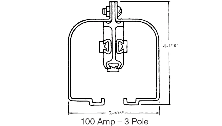
Feedrail Coupling Plate Set for FR100 Series (Feedrail '100')
Item Number: FR102
Set of two heavy gauge pressed steel plates serves as a coupling for track sections and as a hanger for attaching to supporting members. Removable snap on covers permit ready access to the bus bar joints.

Feedrail Dead End Cap for FR100 Series (Feedrail '100')
Item Number: FR107
Set of two heavy gauge pressed steel plates and box for closing the end of a track run. Also serves as a hanger fo attaching to supporting members. Include a trolly stop.

Feedrail Center Feed Box for FR100 Series (Feedrail '100') - 3 Pole, 100 Amp
Item Number: FR103
Set of two heavy gauge pressed steel plates, box and covers, through which electrical connection to the power supply is made between any two track sections. Serves as a track coupling and hanger for attaching supporting members. Has concentric knockouts for 3/4", 1", 1-1/4" or 1-1/2" conduit in the top. complete with pressure type terminals accommodating No. 14 to 0 stranded wire.

Feedrail Reversible End Feed Box for FR100 Series (Feedrail '100') - 3 Pole, 100 Amp
Item Number: FR109
Set of two heavy gauge pressed steel plates and a two piece box through which electrical connection to the power supply can be made at the end of a track run. Reversible box permits conduit connection at top, bottom of end. Has concentric knockouts for 3/4", 1', 1-1/4" or 1-1/2" conduit. Also serves as a hanger for attaching track to supporting members. Complete with pressure type terminals accommodating No. 14 to 0 stranded wire.

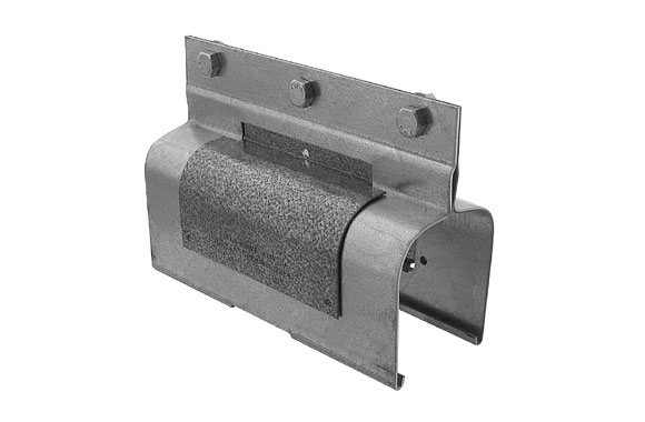
Feedrail Auxilliary Track Hanger Set
Item Number: FR140
Heavy gauge pressed steel plates for intermediate mounting of track sections to supporting members. Fits over top of straight track housing rib at any of the insulator bolting points. Complete with 3/8" mounting bolt.

Feedrail Transfer Point Hanger Set for FR100 Series (Feedrail '100')
Item Number: FR124
Set of two heavy gauge pressed steel plates formed to match flared ends of transfer sections. Use as hanger for attaching to supporting mebers at open end of transfer track sections.

Electro-Rail Clevis Support for Tie Rod Installations
Item Number: 12283
Clevis support for tie rod applications. Malleable iron, with 3/8" cross bolt and 3/8"-16 tapped hole for tie rod. Must be used in conjunction with FRS-124 and FRS-105 track hangers.

Feedrail Single Trolley, Non-Fusible with Roller Contacts - 3 Pole, 20 Amp
Item Number: FR724
Single trolley, non-fusible, for FR100 Series (Feedrail "100"). 20 amps, 3 poles, 600 VAC - 250 VDC, roller contact.

Feedrail Single Trolley, Non-Fusible with Brush Contacts - 3 Pole, 30 Amp
Item Number: FR780
Single trolley, non-fusible, for FR100 Series (Feedrail "100"). 30 amps, 3 poles, 600 VAC - 250 VDC, brush contact.

Feedrail Duplex Trolley, Non-Fusible with Roller Contacts - 3 Pole, 40 Amp
Item Number: FR727
Duplex trolley, non-fusible, for FR100 Series (Feedrail "100"). 40 amps, 3 poles, 600 VAC - 250 VDC, roller contact.

Feedrail Duplex Trolley, Non-Fusible with Brush Contacts - 3 Pole, 40 Amp
Item Number: FR782
Duplex trolley, non-fusible, for FR100 Series (Feedrail "100"). 60 amps, 3 poles, 600 VAC - 250 VDC, brush contact.

Feedrail Trolley with Hanger Cabinets - 3 Pole, 20 Amp
Item Number: FR705
Trolley with hanger cabinets for FR100 Series (Feedrail "100"). 20 amps, 3 poles, 600 VAC - 250 VDC, roller contact.

Feedrail Trolley with Hanger Cabinets - 3 Pole, 30 Amp
Item Number: FR785
Trolley with hanger cabinets for FR100 Series (Feedrail "100"). 30 amps, 3 poles, 600 VAC - 250 VDC, brush contact.

Feedrail Fusible Trolley with Beveled Cabinets and 30 Ampere Recepticle - 3 Pole, 30 Amp
Item Number: FR870
Trolley with beveled cabinets, fusible, with 30 ampere recepticle. For FR100 Series (Feedrail "100"). 3 poles, 250 A.C. - 250 D.C., 30 amps. Brush contact and dead front fuse block.

Feedrail Non-Fusible Trolley with Box Cabinet and Cable Clamp - 3 Pole, 20 Amp
Item Number: FR741
Trolley with box cabinet, non-fusible, without recepticle, with cable clamp. For FR100 Series (Feedrail "100"). 3 poles, 20 amps, 600 VAC - 250 VDC. Roller contact.
Feedrail Non-Fusible Trolley with Box Cabinet and Cable Clamp - 3 Pole, 30 Amp
Item Number: FR784
Trolley with box cabinet, non-fusible, without recepticle, with cable clamp. For FR100 Series (Feedrail "100"). 3 poles, 30 amps, 600 VAC - 250 VDC. Brush contact.

Feedrail Fusible Trolley with Box Cabinet and Cable Clamp - 3 Pole, 20 Amp
Item Number: FR743
Trolley with box cabinet, fusible, without recepticle, with cable clamp. For FR100 Series (Feedrail "100"). 3 poles, 20 amps, 600 VAC - 250 VDC. Roller contact and open front fuse block.

Feedrail Fusible Trolley with Box Cabinet and Cable Clamp - 3 Pole, 30 Amp
Item Number: FR788
Trolley with box cabinet, fusible, without recepticle, with cable clamp. For FR100 Series (Feedrail "100"). 3 poles, 30 amps, 600 VAC - 250 VDC. Brush contact and open front fuse block.

Feedrail Crane and Hoist Single Trolley, Non-Fusible - 3 Pole, 30 Amp
Item Number: FR706
Crane and hoist trolley for FR100 Series (Feedrail "100"). Single trolley, non fusible. 3 poles, 30 amps. Brush contact. Voltages - 220 VAC: 7-1/2HP, 440 VAC: 15HP and 550 VAC: 20HP. Note: Not for use with Transfer Track.

Feedrail Crane and Hoist Single Trolley, Non-Fusible with Receptacle - 3 Pole, 30 Amp
Item Number: FR706-8304
Crane and hoist trolley for FR100 Series (Feedrail "100"). Single trolley, non fusible, wired with a 30 amp recpetacle. 3 poles, 30 amps. Brush contact. Voltages - 220 VAC: 7-1/2HP, 440 VAC: 15HP and 550 VAC: 20HP. Note: Not for use with Transfer Track.

Feedrail Crane and Hoist Duplex Trolley, Non-Fusible - 3 Pole, 60 Amp
Item Number: FR706D
Crane and hoist trolley for FR100 Series (Feedrail "100"). Duplex trolley, non fusible. 3 poles, 60 amps. Brush contact. Voltages - 220 VAC: 15HP, 440 VAC: 30-HP and 550 VAC: 40-HP. Note: Not for use with Transfer Track.

Feedrail Single Transfer Type Trolley - 3 Pole, 30 Amp
Item Number: FR774
Transfer type single trolley - non fusible, for use on track runs which include transfer gaps. 3 pole, 30 amp.

Feedrail Single Transfer Type Trolley with Receptacle - 3 Pole, 30 Amp
Item Number: FR774-8304
Transfer type single trolley - non -fusible, with receptacle, Wired complete with Ever-Lok® 30 Ampere receptacle. 3 pole, 30 amp.