Feedrail FRS300 Plug-In Series
Overhead Electrification Systems for Stationary Plug-In Service
General Information:Feedrail® systems are capable of providing multi-purpose trolleys or stationary plug-ins for installations requiring a source of electrical power which can be reconfigured without rewiring. These systems provide moveable outlets for electrical power along their entire length. The systems are especially suited for use where conventional wire systems would be cumbersome and costly. Plug-in Jacks with stationary power take-offs, are available for all Feedrail® systems. The busway-supported outlets called “trolleys” (Feedrail® 60 system only) make contact with the enclosed bus bars and provide a continuous moveable connection for electrical devices. The trolleys are easily inserted and removed through door-busway sections. As additional outlets are needed, trolleys (Feedrail® 60 System only) or stationary plug-ins can be quickly and efficiently inserted, their numbers being limited only by the current-carrying capacity of the busway and the capacity of each outlet. Reliable design assures uniform contact pressure, limiting work stoppages due to electrical and mechanical interruptions in supplying power. Advantages of these systems include low installation costs with complete re-usability; ease of adding outlets as required; electrical and personnel safety; compactness; dependability and minimum maintenance expense. All “busway (track) sections” are factory assembled for ease in handling and rapid installation. No special tools are required. Systems are designed for indoor use in non-hazardous, non-corrosive, dry atmosphere. UL & CSA ListedFeedrail® is listed by Underwriter's Laboratories, Inc. (U.L.) under BUSWAYS AND ASSOCIATED FITTINGS (File E11348 for Feedrail® / File E165922 for Electro-Rail® ) and as a CRANE AND HOIST ELECTRIFICATION SYSTEM (File E31188 for Feedrail® ). Feedrail® is also listed by the Canadian Standards Association (C.S.A.) under WIREWAYS AND BUSWAYS (File LL-7907 for Feedrail® / File LL 103287-1 for Electro-Rail® ).
|
Basic Information:
More Information:
This short video (no sound) shows the basic components and set up for the Feedrail® FRS100, 200 & 300 Series. |
FRS300 Series Plug-In Service — Design and Construction
Current Carrying Capacity
(Click image for full-size view)Track Rating: 50 amps continuous
Plug-In Jack Rating: 15 amps continuous
Voltage
300 VAC, max
Track
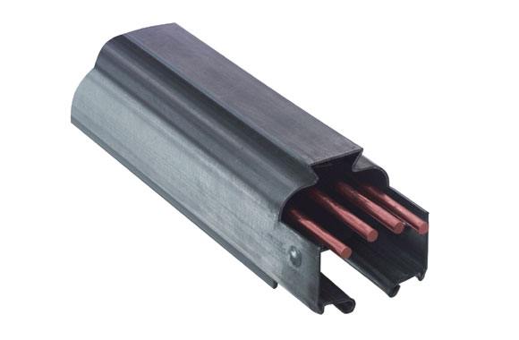
Track sections consist of a one-piece streamlined 18-gauge zinc coated steel housing and the enclosed current carrying bus bars and insulators, all facory assembled in convenient lengths ready for easy, fool-proof installation on the job.
Buss bars are of hard-drawn copper. They are amply proportioned to carry the specified current of 40 amperes per pole continuously, without overheating. Bus bar connectors assure full current carrying capacity across the joints. Insulators are made of a high insulating and arc-resistent material. They are locked in place on 9-5/8” centers.
A plastic polarization strip is incorporated in the track housing to insure proper insertion of the polarized Plug-In Jack. When inserted, the Plug-In Jack is automatically grounded to the track system for safe operation.
Track Supports
Steel clamp type track hangers for supporting track sections from strap or rod. Track should be supported by a minimum opf two track hangers per section. Track may also be supported on 10' centers at track joints when used with Duplex Track Hangers.
Plug-In Jacks
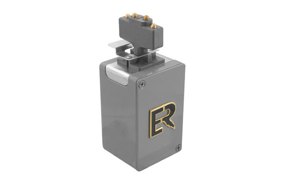
Plug-In Jacks are available for 2, 3 and 4-pole systems. Plug-In Jacks are available with a galvanized steel outlet box with clamp for fast, easy wiring. The Jack has spring-loaded brass contacts for direct positive contact with the bus bars.
Plug-In Jacks can be inserted into the track slot at any point. A quarter turn, after insertion, makes electrical contact and locks the Jack in place.
Grounding
For the safety of personnel, the track casings of the Feedrail® system may be used as an equipment grounding conductor for grounding equipment through the individual Plug-In Jacks.
Equipment grounding may be made by using the screw on the underside of the Plug-In Jacks or on Jacks having cabinets or boxes by using the grounding screw within the box. Track housing must be grounded through conduit or other suitable means.
Feedrail® FRS 300 Series systems are designed for indoor service in essentially dry locations. Feedrail® systems are electrified tracks in which the current carrying components are enclosed in protective steel housings. Plug-In jacks take off current anywhere along the length of the system and supply a stationary source of electric power. Feedrail® FRS300 Series systems have been specifically developed to provide safe electrification for assembly or production lines, lighting, and sewing trade applications.
The Feedrail FRS300 Series systems are made up of standardized units, factory assembled for fast, complete installation and without on-site fabrications.
Evaluation of Feedrail® FRS300 Busway System
Feedrail® FRS300 4 Pole System
(Stationary Plug-in System)
Electrical Current Carrying Capacity
Busway (track) rating: 50 amperes continuous. PLUG-IN JACKS rated at 15 amperes continuous.
Voltage
Busway (track) 300 Volts.
Supporting the Busway
Busway (track) should have a minimum of two busway hangers per section for support. Additional Busway hangers can be attached at intermediate points. Busway may be supported on up to 10' centers at busway joints when used with duplex track hangers. Please refer to Busway Hanger Section for available styles.
Busway
Busway (track) sections consist of a one-piece streamlined 18-gauge zinc coated steel housing and the enclosed current carrying 4 round bus bars and insulators. Busways are factory assembled in convenient 10 foot lengths and ready for easy, fool-proof on-the-job installation.Bus bars are of hard drawn copper. Designed to carry the specified current of 50 amperes per pole continuously, without overheating. Bus bar coupling sets provide full current carrying capacity across the joints. Insulators are made of high insulating and arc-resistant material.
Plug-Ins
A plastic polarizing guard in the busway housing insures proper insertion and grounding of the polarized plug-in jack. Designed for applications where the frequent movement of a trolley is not required (i.e., sewing rooms, connecting light fixtures, small tools, etc.). Insertion into a busway (track) section can be at any point of busway. After insertion a one quarter turn makes electrical contact with bus bars and locks the plug-in securely in place.
FRS300 Component Ordering Guide
- One coupling set (ERS-402-4) less than the number of track sections (ERS-300M) in busway run.
- One dead end cap set (ERS-307-4).
- One end feed set (ERS-306-4).
- Two hangers for each 10 foot busway section (select type best suited for your requirements).
- Select number of plug-ins required either (ERS-351M or ERS-350M).
FRS300 Mounting Methods
Examples of the methods commonly used for mounting 4 pole system busway runs are shown below. These methods can be used in existing plants as well as in new constructions. Engineers and contractors can devise other methods to suit special installations. In every case the mounting should be designed to insure a rigid installation in both horizontal and vertical alignment. Rod or strap supports should not exceed 2 feet in length without sway bracing.
As an aid in planning mountings, the basic dimensions of the Feedrail® 4 pole systems are shown below. These are offered as a guide only.
Wall Mounting |
Wood Ceiling Mounting |
Wood Beam Mounting |
Concrete Ceiling Mounting |
Basic Dimensions & Mounting Methods
Basic Dimensions
As an aid in planning mountings, the basic dimensions of the Feedrail® Plug-In system is shown below. These are offered as a guide only.
Mounting Methods
Examples of the methods commonly used for mounting the Feedrail Plug-In system is shown below. These methods can be used in existing plants as well as in new buildings. In every case the mounting should be designed to insure a rigid installation in both horizontal and vertical alignment.
Click image for full view.
Bus Bar Arrangement
 50 Amp 4 Pole 300 Volt |
 50 Amp 3 Pole 300 Volt |
 50 Amp 2 Pole 300 Volt |
Note: Other bus bar configurations are available on special order. The standard systems shown are preferred for electrical noninterchangeability of track and Plug-In Jacks.
Typical Electrical Systems for Various Applications
| Applications | Electrical System | Connections-Grounding |
|---|---|---|
For Single Phase
|
Single Phase 2P, 3W 120V Equipment Ground Wire thru Casing |
 |
| Single Phase 2P, 3W 208/220V Equipment Ground Wire thru Casing |
|
|
| Single Phase 3P, 4W 208/220V Equipment Ground Wire thru Casing |
 |
|
Applications |
Electrical System |
Connections-Grounding |
For Three Phase
|
Three Phase 3P, 4W 208V or 220V Equipment Ground Wire thru Casing |
|
| Three Phase 4P, 5W 120/208V or 120-277V with use of 2 neutral conductors Equipment Ground Wire thru Casing |
 |
Typical Specification
As an aid to preparing specifications for a Feedrail® installation, the following wording is suggested. You will note this specification contains the primary electrical and mechanical features of the Genuine Feedrail® System.
FRS300 SERIES Plug-In Service
The Plug-In Busway System shall be of the metal enclosed type with internally track-supported Plug-In Jacks as manufactured by:
Genuine Feedrail®
Industrial Products
The System shall have a voltage rating 300 Volts A.C. or D.C. (2 pole) (3 pole) (4 pole) and a continuous current carrying capacity of (40) (50) Amperes per pole. The full current carrying capacity of the system shall be maintained throughout.
The System shall permit longitudinal movement of the housings and bus bars, independent of each other, in order to allow for unequal expansion and contraction as a result of temperature changes.
The System shall consist of standardized, interchangeable, Feedrail® units - track sections, coupling sets, dead end caps, track hangers and power takeoff Jacks as called for on the plans.
Track sections shall be one-piece, 18 gauge, rolled, zinc-coated sheet steel enclosures having a continuous slot in the bottom and a heavy keystone shaped rib in the top. Round copper bus bars, capable of carrying (40) (50) Amperes per pole continuously without overheating, shall be mounted within the steel enclosure on arc-resistant insulators.
A plastic strip bumper guard shall be incorporated in the track housing to insure proper insertion of the polarized Plug-In Jack.
When inserted, the Plug-In Jack is automatically grounded to the track system for safe operation.
Track supported Plug-In Jacks shall be Cat.No._____________________________ as listed in the Feedrail Catalog. The Jack shall have spring-loaded contacts for direct, positive contact with the bus bars.
Plug-In Jacks can be inserted in the track slot at any point. A quarter turn, after insertion, makes electrical contact and locks the Jack in place.
Installation Planning
Before a Feedrail® system can be planned or an estimate of the cost prepared, the electrical and mechanical requirements that the system must meet should be known. The following outlines list the basic data needed for all applications and the additional data required for various specific applications.
Basic For All
- Describe in detail the purpose for which the Feedrail system will be used. Will it be used with existing equipment?
- How many conductors will be required?
- What voltage and current is to be applied to each conductor? Where is the power source located?
- Details about any special requirements or conditions which the installation must meet such as moisture, corrosive fumes, high or low temperatures, etc.
For Electric Cranes
- Sketch giving number, location, length of crane runways and length of bridge. Show location of building expansion joints or expansion joints in the structure from which the Feedrail® will be supported.
- How many conductors will be required on each bridge run? How many for power? For control? How much current must each conductor carry?
- What is the maximum travel speed of the bridge? of the hoist?
- List of the crane's motors - main hoist, auxiliary hoist, bridge travel, trolley travel - giving the type (D.C., wound rotor, squirrel cage, etc.) of each motor and its horsepower and full-load ampere rating.
For Electric Hoists
- Plan view sketch of the rail system on which the hoists will travel, giving the length of run, of straight sections, radii of any curves and dimensions of any switches. What is the minimum distance from Feedrail to monorail in order to clear hoist? Show location of building expansion joints or expansion joints in the structure from which the Feedrail® will be supported.
- How many hoists will be used and what is the horsepower and full load current rating of each? Include horsepower and full load current rating of travel motors of any of the hoists that are motor propelled. What are the maximum travel speeds?
For Moving Test Lines
- Plan view sketch with dimensions showing the length of straight sections and radii of any curves, indicate the number of outlets required. If there are any sections along the run where test current will not be required, indicate their location and extent.
- What type of equipment will be tested.
- Give weight of units to be supported by the system.
- What amperage range and what fusing arrangements will be required.?
For Production Machines
- Plan view sketch with dimensions showing the location of the Feedrail® system.
- Indicate the number of conductors required and give voltage and amperage requirements of each. Give horsepower and full load current rating of each motor.
- List any other equipment that will be powered by the Feedrail and give its full load current rating.
For Special Requirements
- Plan view sketch with all dimensions which are necessary to make clear the location and extent of the Feedrail system, and the radii of any curves it may contain. Show the location of the power source.
- Full details about equipment which will be operated from the system, including:
- Horsepower and full-load current rating of any electrical motors.
- Weight of any equipment to be supported by the system.
- Fusing arrangements required.
- Number of outlets needed.
Engineering Cooperation
Working out the details of a Feedrail® system installation is not difficult once all the electrical and mechanical requirements have been definitely determined.
Installation Instructions for FRS-307-4
Mounting Dead End Cap on Busway (Track) Housing
 Place bus stops (1) over bus bars (2) and push them on all the way. Take the 2 halves of the coupling plate (3) and hook them to the bottom of the busway (track) housing and swing up so the holes are placed over the dimples (4) on the busway housing. Place bus stops (1) over bus bars (2) and push them on all the way. Take the 2 halves of the coupling plate (3) and hook them to the bottom of the busway (track) housing and swing up so the holes are placed over the dimples (4) on the busway housing. |
 Hold the coupling plate (1) and insert screws (2) to fasten the coupling together. Loosen screws on end plate (3) to allow sliding into position on coupling plate (1). Retighten screws on end plate. Hold the coupling plate (1) and insert screws (2) to fasten the coupling together. Loosen screws on end plate (3) to allow sliding into position on coupling plate (1). Retighten screws on end plate. |
 Place cover plate (1) onto coupling plate (2). Insert screws (3) on coupling and the installation of dead end cap is completed. Place cover plate (1) onto coupling plate (2). Insert screws (3) on coupling and the installation of dead end cap is completed. |
Installation Instructions for FRS-306-4
Mounting End Feed Box to Busway (Track) Section
 Place connectors (1) of plastic insulator (2) onto bus bar ends so that the connectors are half way on. Tighten the 4 screws (3) on the connectors to hold the insulator secure. Take the 2 halves of the coupling plate (4) and hook them to the bottom of the busway (track) housing and swing up so the holes are placed over the dimples (5) on the busway housing. Place connectors (1) of plastic insulator (2) onto bus bar ends so that the connectors are half way on. Tighten the 4 screws (3) on the connectors to hold the insulator secure. Take the 2 halves of the coupling plate (4) and hook them to the bottom of the busway (track) housing and swing up so the holes are placed over the dimples (5) on the busway housing. |
 Hold the coupling plate (1) and insert screws (2) to fasten the 2 halves of coupling plate together. Then place end feed box (3) over coupling plate (1) as illustrated. Line up holes in box and coupling (4) and insert and tighten screws (5). Hold the coupling plate (1) and insert screws (2) to fasten the 2 halves of coupling plate together. Then place end feed box (3) over coupling plate (1) as illustrated. Line up holes in box and coupling (4) and insert and tighten screws (5). |
 Place cover (1) over box (2) as illustrated. Insert screws (3) and tighten. The end feed box installation is completed. Place cover (1) over box (2) as illustrated. Insert screws (3) and tighten. The end feed box installation is completed. |
Preventative Maintenance
At all times Feedrail® equipment should be so protected and maintained as to be kept clean and dry.
Before the Feedrail system is placed in operation, it should be thoroughly checked for horizontal and vertical alignment, adequate track support and free movement of trolley travel throughout the entire track run. All track, bus bar and feed connections should be mechanically tight. The system should be checked for possible grounds or short circuits. Any paint, grease, or other foreign matter accumulated during construction should be removed from the bus bars, insulation and track interior. Blow out all dust and other loose particles from inside the track.
Expansion sections, when used, must be properly adjusted, located and supported in accordance with installation instructions. Check bus bars and casing for accurate alignment.
Feedrail® is both an electrical and a moving mechanical system and therefore should be included as a part of your Preventive Maintenance Program.
Electrical Maintenance requires:
- Keeping the system dry and clean to prevent electrical leakage or "shorts" across the insulation.
- Maintaining electrical continuity by keeping bus bar contact surfaces clean and joints tight.
Mechanical Maintenance requires:
- Preventing excessive wear.
- Replacing parts showing excessive wear.
The following Preventive Maintenance procedure, periodically performed, is recommended:
- Remove, thoroughly clean all trolleys and lubricate the wheels. Feedrail® recommends Grade #1 Bearing Grease. This is softer grease than #2 and allows the grease to penetrate the bearings easier. Inspect contacts for excessive wear. Replace worn wheels and contacts.
- Clean bus bars with Feedrail® Bus Bar Cleaner.
- Blow out all foreign particles which have accumulated inside the track.
- Check trolleys for free movement within the track.
- Check all track supports, track joints, bus bar and feed connections for tightness. This procedure should be repeated at regular intervals, consistent with the severity of the operations and usage of the system. Plants operating two or three shifts will require more frequent inspection of the Feedrail® equipment.
Feedrail® is not normally recommended for installations subject to vibration, frequent electrical overload, corrosive fumes and other abnormal conditions. However, should such conditions exist, more frequent inspections and maintenance will be required.
Before additional electrical loads are added to the system, it should be determined that sufficient capacity is available.
Build Your Feedrail FRS300 Series Plug-In Service System
All of the components you'll need to build a brand new Feedrail FRS300 Series system have been organized below by category. It is recommended that you start with Track Sections and work your way through each category in the order they're presented. If you have any questions, please contact us and one of our highly trained Feedrail specialists will respond shortly.
 Track Sections |
 Track Accessories & Hangers |
 Plug-In Jacks |
 Replacement Parts |
Shop for Feedrail FRS300 Series Plug-In Service System Components, Parts & Accessories
All components, parts and accessories for the Feedrail FRS300 Series Plug-In Service System can be found below. Use the product filter menu to narrow your search.
Track Accessories
Track Sections
Track sections consist of a one-piece streamlined 18-gauge zinc coated steel housing and the enclosed current carrying bus bars and insulators, all factory assembled in convenient lengths ready for easy, fool-proof installation on the job. No special tools required. 10' and 5' are standard lengths. Other lengths furnished on special order.
![]()
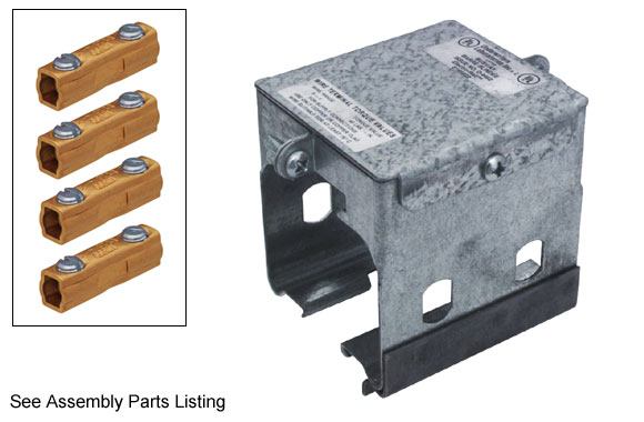
Track Sections, Built-In Center Feed
Supplied with feed box built-in, through which electrical connections to the power supply can be made. Has concentric knockouts for 1" and 1-1/4" conduit. Terminals accommodate No. 14 to No. 6 standard wire.
Plug-In Jacks
Replacement Parts


Electro-Rail 10’ Straight Track – 4 Pole, 50 Amp
Item Number: 11669
10 foot straight track section. 4 pole, 50 amp, 300 volt AC/DC busway. Fits Feedrail FRS300 Plug-In Series. Track shipped with polarization strips and slot enclosures.

Electro-Rail 5’ Straight Track – 4 Pole, 50 Amp
Item Number: 11680
5 foot straight track section. 4 pole, 50 amp, 300 volt AC/DC busway. Fits Feedrail FRS300 Plug-In Series. Track shipped with polarization strips and slot enclosures.

Electro-Rail 10’ Track with Built-In Center Feed – 4 Pole, 50 Amp
Item Number: 11668
10 foot straight track with built-in center feed. 4 pole, 50 amp, 300 volt AC/DC busway. Fits Feedrail FRS300 Plug-In Series. Track shipped with polarization strips and slot enclosures.

Electro-Rail Coupling Set – 4 Pole, 50 Amp
Item Number: 11676
4 pole, 50 amp coupling set for FRS300 Plug-In Series. Consists of side plates, cover and bus bar connectors used to join track sections. One coupling is required for every two sections of track joined.

Electro-Rail Dead End Cap – 4 Pole
Item Number: 11679
4 pole end cap for FRS300 Plug-In Series. Used for closing the end of a track run.

Electro-Rail End Feed Set – 4 Pole, 50 Amp
Item Number: 11678
50 amp, 4 pole end feed. Used for connection to power supply at the end of track run. Serves as end cover. Concentric knockouts at end (1/2 or 3/4 conduit). Terminals included accomodate No. 14 to No. 6 strand wire. Fits FRS300 Plug-In Series.

Electro-Rail Tie Rod Hanger
Item Number: 12291
Track hanger for tie rod. Fits FRS100 & FRS200 Series, also FRS300 Plug-In Series. Allows direct attachment of 3/8" tie rods at any point between track joints. Permits easy leveling of track sections. When used with curved track, field notching of track top flange is required for clearance of clamping bolt. A minimum of two track hangers required for each straight track section.

Electro-Rail Straight Track Hanger
Item Number: 12284
Track hanger for FRS100 & FRS200 Series, also FRS300 Plug-In Series. For mounting straight track sections. Mounting hole will take 3/8" diameter bolt. They can be attached to straight track at any point between track joints. Not suitable for curved track sections. Minimum of two track hangers required for each straight track section.

Electro-Rail Clevis Support for Tie Rod Installations
Item Number: 12283
Clevis support for tie rod applications. Malleable iron, with 3/8" cross bolt and 3/8"-16 tapped hole for tie rod. Must be used in conjunction with FRS-124 and FRS-105 track hangers.

Electro-Rail Duplex Busway Hanger Set
Item Number: 11675
Duplex busway hanger set. For FRS100 & FRS200 Series, also FRS300 Plug-In Series. For 10' support spacing to be used at track joint over coupling.

Electro-Rail Low-Level Track Hanger
Item Number: 12363
Hanger (low level). For FRS100 & FRS200 Series, also FRS300 Plug-In Series. Used in place of track hanger FRS-105 where head room is limited. Takes 3/8" diameter bolts. Can be attached to straight track at any point between track joints. Not suitable for curved track. Minimum of two track hangers required for each straight track section.

Electro-Rail Non-Fusible Plug In Jack with 6" Leads – 4 Pole, 15 Amp
Item Number: 11470
Non-fusible plug in jack with 6" leads. For FRS300 Plug-In Series. 4 poles, 15 amps, 300 volts AC.

Electro-Rail Non-Fusible Plug In Jack with Box and Cable Grip – 4 Pole, 15 Amp
Item Number: 11472
Non-fusible plug in jack w/box and cable grip. For FRS300 Plug-In Series. 4 pole, 15 amp, 300 Volts AC.

Electro-Rail Non-Fusible Plug In Jack with Box and NEMA 5-15R Receptacle
Item Number: 11474
Non-fusible plug in jack w/box and NEMA 5-15R receptacle. For FRS300 Plug-In Series. 2 poles, 15 amp, 120 volts AC.

Electro-Rail Fusible Plug In Jack with Box and Cable Clamp – 4 Pole, 15 Amp
Item Number: 11677
Fusible plug-in jack w/box and cable clamp. For FRS300 Plug-In Series. 4 poles, 15 amps, 300 volts AC. Fuses are not included. Fusible with 9/16" x 2" cartridge fuses.

Electro-Rail Replacement Only 4 Pole Jack Assembly
Item Number: 11677S
4 pole jack assembly for FRS300 Plug-In Series. 4 poles, 15 amps, 300 volts AC.

Electro-Rail Fusible Plug-In Jack with Cabinet and NEMA 5-15R Receptacle – 2 Pole, 15 Amp
Item Number: 11681
Fusible plug-in jack w/cabinet and NEMA 5-15R (straight blade) receptacle. For FRS300 Plug-In Seies. 2 pole, 15 amps, 120 volts AC. Fuses are not included. Fusible with 9/16" x 2" cartridge fuses.

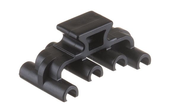
Electro-Rail Bus Bar Insulator for FRS300 Plug-in Series
Item Number: 13853
Bus bar insulator for FRS300 Plug-In Series. For No. 11669 "Electro-Rail" E300 Plug-In Busway and FRS300 Series (Plug-In Service)

Electro-Rail 10’ Straight Track Casing for FRS100, FRS200 & FRS300 Series
Item Number: 12277C
Electro-Rail 10 foot straight track casing for FRS100, FRS200 & FRS300 Series.

Electro-Rail Straight Track End Cap for FRS100, FRS200 & FRS300 Series
Item Number: 11669EC
Electro-Rail straight track end cap for FRS100, FRS200 & FRS300 Series.